The Pulsed-Field Magnetometer (PFM) is an internationally recognised standard device for the complete characterisation of modern magnetic materials. The PFM is an accurate and reliable magnetometer suitable for the scientific investigation of ferromagnetic materials. The fast measurement also makes the PFM the ideal tool for bulk testing, i.e. in quality assurance applications.
Permanent magnetic materials are characterised and graded by their response to an externally applied magnetic field, this is plotted as a hysteresis loop. In the second quadrant of the hysteresis loop the applied magnetic field is in opposition to the sample magnetisation, this quadrant is referred to as the demagnetisation curve, it is of special interest because this is where most magnetic machines operate.
Historically demagnetisation curves were measured using a permeameter. A permeameter uses an iron-core, closed-magnetic-circuit to deliver a uniform magnetic field to the sample. However, modern hard magnetic materials often cannot be accurately characterised using a permeameter because the high coercive fields required will saturate the iron core thus corrupting the measurement.
In contrast, PFMs are open-magnetic-circuit devices, such that even for the hardest magnetic materials the applied magnetic field remains uncorrupted.
Hirst Magnetic Instruments are the world leaders in PFM technology, working closely with the International Electrotechnical Commission (IEC) IEC TR62331 in order to define the standard methodology for the characterisation of permanent magnetic materials.
Hirst scientists have developed algorithms that can accurately and precisely calculate the equivalent closed-circuit demagnetisation curve based on the open- circuit measurement.
How does a PFM work ?
A PFM is a stand-alone magnet characterisation instrument. It consists of a capacitor bank, a magnetisation coil, a pick-up coil, Peltier coolers, a sample chiller for measurements down to –40°C, and a sample heater for measurements over 230°C – depending on the product variant. The PFM is controlled by a PC which also stores all measurements in an integrated database. To operate a PFM, a sample is placed onto a sample holder. The sample holder is inserted into the PFM. Heating and cooling of the sample are integrated into the measurement process.
The applied field
The applied field is a single period sine-wave pulse with a maximum amplitude in excess of 10 Tesla. As such the PFM captures the full hysteresis loop. It is in the nature of pulsed- field measurements that rate dependent features are present in the hysteresis loop, these are due to eddy-current effects, for each measurement the PFM applies two pulses at different frequencies, this allows for rate dependent effects to be calculated out of the final result.
Eddy-Current Correction (F-2F)
When a changing magnetic field strength is applied to any electrically conductive material, eddy currents will be generated. These eddy currents will in turn, generate magnetic fields of their own. Care must be taken in magnetic measurement to avoid or remove these effects.
Hirst Magnetic Instruments Ltd. have been been granted patents for a process known as F-2F in which 2 pulses (one long and one short) are used and when combined mathematically can remove the eddy current effects for Pulsed Field Magnetometry measurements.
Hirst uses the F-2F algorithm in order to calculate the hysteresis loop that would be obtained from a zero-frequency measurement. F-2F has been verified to produce the same results as a static measurements obtained from a vibrating sample magnetometer.
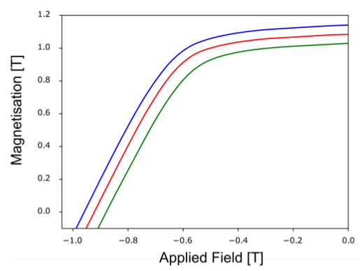
Illustration of the results from the F-2F algorithm. Blue line: Demagnetisation curve obtained from a short pulse at double frequency. Red line: Demagnetisation curve obtained from a long pulse at single frequency. Green line: Calculated zero-frequency demagnetisation curve.
Measured Magnetic Moment
The pick-up coil measures the magnetic moment of the sample, whilst remaining insensitive to uniform fields. In this way the pick-up coil rejects the applied magnetic field. The pick-up coil is maintained at a constant temperature in order to ensure the precision of the measurement.
Self-Demagnetisation Field Correction
The PFM applies a standard self- demagnetisation factor (SDF) to correct for sample geometry and aspect ratios, this feature has been on many previous generations of machine including the latest PFM08 range. It should be noted that this SDF-corrected demagnetisation curve is not yet equivalent to a permeameter curve.
Permeameter Correction – SDFF™
The PFM08 generation of machine integrates a new Hirst algorithm that accurately maps the open-circuit measurement onto a closed-circuit, permeameter equivalent measurement. This approach is called Self Demagnetisation Field Function or SDFF™ technology generates an open to closed circuit mapping (O2C™) giving accurate closed loop permeameter like measurements and the calculated demagnetisation curve matches with a permeameter measurement with a difference typically less than 1%. This precision has been verified for all grades of Neodymium and Samarium Cobalt, many sample geometries, and for the full temperature range of the PFM.
In order to validate this algorithm, Hirst have worked in collaboration with the UK National Physics Laboratory, the University of Exeter, and the National Institute of Metrology in China.
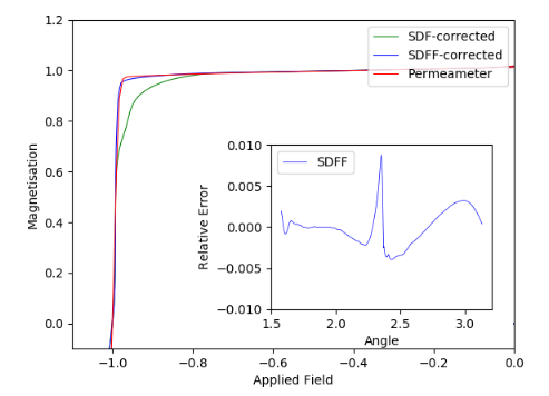
Demagnetisation curves for typical a neodymium magnet. Green line: The simple SDF-corrected curve. Red line: the demagnetisation curve obtained using a permeameter. Blue line: the equivalent closed-circuit curve obtained from the Hirst PFM. Thus this unique Self De-magnetization Field Function SDFF™ (patented) accurately generates an open to closed circuit mapping (O2C™) for the magnet sample giving accurate closed loop magnet parameters. These accurately extract critical parameters: – Remanence: Br, Coercivity: HcJ, HcB, Maximum energy product: BHMax, Saturation values: Hsat, Jsat, Squareness Coefficients: Hk, Hk/HcJ, Sa, and more are all automatically extracted from every measurement and displayed separately alongside JH and BH loops. The first generation of Hirst industrial PFM was launched in 1998 and the company won an Institute of Physics business award for the SDFF™ technology in 2020.
Inset: The relative difference in load line length between the PFM equivalent per- meameter curve and the measured permeameter curve. The x-axis is the angle between load lines and the horizontal. This shows the maximum deviation between a PFM running SDFF and the permeameter is less than 1%.
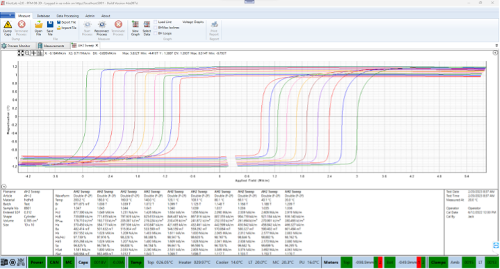
Hirst Lab software
The Hirst Lab software combines all of Hirst’s expertise and PFM technology into a single, easy-to-use package. The software manages the operation of the machine, and maintains a database with the history of all measurements.
A flexible plotting tool provides multiple views of the measured data. By default the SDF -corrected demagnetisation curves are plotted alongside the SDFF(TM) (permeameter equivalent curve) on the generation 8 machines which run HirstLab v2 as standard.
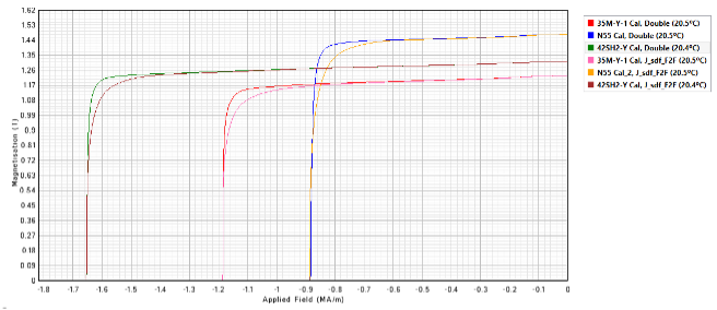
Above the SDFF™ curves alongside the SDF curves to the showing the sharp permeameter like results the PFM08 range delivers. Only the SDF curve was available on the generation 7 machines (PFM12 and PFM14).
The generation 8 PFMs can measure manually loaded virgin or pre-magnetised permanent magnets and measure their full 4 quadrant hysteresis loop in a fraction of the time taken by any other technique.
The PFM extracts all key magnetic parameters automatically and is controlled via a comprehensive windows-based application with extensive database facilities storing full data on every single measurement. Data can also be exported in a variety of formats. The system offers repeatability of measurements at speeds that are simply unattainable with other methods of measurement.
Hirst Lab can produce a detailed report describing the characteristics of the measured sample.